Quick start basics - Your first simulation session .
With GSP you can view the steady state and transient operating lines in the components using maps, like the compressor and turbine.
| 2. | Select the Map tab sheet. |
This tab sheet contains the filename and design settings for the off-design component map.
| 3. | Click the show graph button of the map tool bar to show the compressor map. |
| 4. | If unchecked, check Map|Scale to Model des. pnt. by clicking on it. |
Now the compressor map is scaled to the model design point. In practice, component maps for specific engines are hard to obtain. For this reason generic maps are used, obtained from similar components having a different scaling. To use the component map it is scaled in the design point for which all values used in the map are known/given.
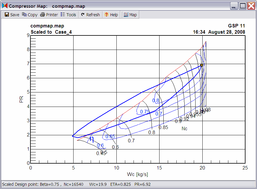
| 5. | Click Map|Draw Transient to display the transient operating line. |
| The graph shown below is the result. If an error message is displayed, check if Map operating curve par.s is checked in the compressor Output tab sheet. If not, check it and redo the actions from Running transient simulations. |
| As can be seen from the graph, the used model is a simplified model, since the operating line is such that the compressor is stalling. In real practice this would be prevented by several bleed measures. |
![]() Component operating line
Component operating line![]() Component operating line
Component operating line


