![]() Component data window
Component data window
![]() Component data window
Component data window
|
<< Click to Display Table of Contents >>
|
  
|
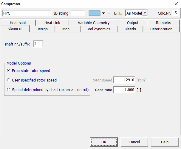
Double-clicking a model component (or icon) from the model window will open the data entry or input window of the selected component. Alternatively right-click the model component to display the component pop-up menu, and select Edit (alternatively press Alt and E key together for a selected or selection of component(s)). A window similar to the picture below will be shown. The window displays various tab sheets where the modeler can setup the specific data for the selected component. The figure below shows an example of the compressor data input window.

•Component name
The user-changeable name used in the textual output to identify the component
•ID string
If user-specified, this string will be added to tabular component output parameter names, replacing the component number
•A color selection interface to determine the background color in the output data table
•The Units field to select the Component unit system
•Calc Nr.
The component number as determined by GSP during model initialization.
•General
The General tab sheet is used to set general component properties, off-design input parameters, component specific data and component options. After a design point has been calculated, the General tab sheet will usually be used to change component properties for analysis of off-design behaviour.
•Design
Design values, always colored navy blue when using standard Windows colours, are used for specification of the component's design point performance parameters. Use this tab sheet only prior to a new design point calculation. Design values are not used during off-design simulation if corresponding variables are specified in other tabsheets. It should be remarked that running a design calculation resets off-design variables to their design variables, if Auto Reset Input to Design is checked in Options|General.
•Map
The Map tab sheet contains the external map file location where the component characteristics are stored in tabular format. GSP component maps represent the non-linear characteristics between 2 to 5 parameters for fan, compressor, combustor and turbine. The map design values are also specified. Scaling of characteristics to the design parameters of the model component is done automatically. For all maps, parameters corrected for component entry conditions are used.
•St.St. OD series or Transient
This tabsheet is either named 'St.St. OD series' or 'Transient' depending on the case type.
In the St.St. OD series or Transient tab sheet input parameters can be specified as a function of point value (St.St. OD) time (transient) in tabular format. With the St.St. OD series/Transient input activated checkbox the time function can be enabled or disabled during transient or steady state series calculations. When disabled or when only one row is present, the Off-design conditions are used instead (and input is constant in time). The navigator buttons are used to add, insert and delete rows, while right-clicking on a value in an existing table and selecting Edit, or double-clicking the value allows you to edit the value.
•Output
In the Output tab sheet parameters which will be included in the results tables can be specified using check boxes. You are adviced to limit the number of output parameters in order to avoid very wide output tables and large amounts of output data which hinder finding the data of interest.
•Deterioration
With the Deterioration tab sheet you can implement deterioration effects for several components. These deterioration effects apply to mass flow, pressure and efficiency.
•Remarks
| The Remarks tab sheet can be used to put down personal remarks. |
For more details read Entering component data.