Shafts transmit mechanical power between components such as turbines, compressors and pumps and are automatically defined in these components. To connect shafts, just specify equal shaft numbers or suffixes for two components in the data specification windows. For example, to connect a compressor to a turbine, set the shaft nr. equal in both General tab sheets. The turbine mechanical power will be added to the shaft while the compressor will absorb all available power from that shaft if the free state rotor speed option is set. Several options are available on how to handle "power surplus or deficit" in a shaft during simulation, depending on the component options set (see Turbine component).
Shafts are not visible on the model panel.
The relation between Shaft speeds and component speeds has changed, the first component defining shaft (usually fan compressor), defines shaft speeds. To output the shaft speed parameters separate Shaft (shaft nr. ID) and Component (component ID) rotor speed output parameters are available in turbo machinery component output tab sheets. Since duplicate output is not allowed, setting output data, for shaft speed for instance, should be done in one of the turbo components the shaft. Alternatively, use the central output functionality of the output parameter tab sheet by selecting component output for turbo components. Setting shaft properties for turbo components will automatically prevent duplicate output.
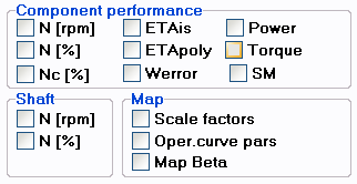
The figure below shows a snippet of the output parameters tab sheet of a turbo component (e.g. compressor, turbine, etc.)

Component parameters, such as rotor speeds and torques, can be selected in the top option box, which can be identified in the output table by the parameter name followed by an underscore and the component number (or the ID string from the component data entry window) (e.g. Nc_4 and PWshaft_4 are corrected speed and power input or output in component nr. 4), while shaft output can be selected in the lower left option box, which can be identified in the output table by the parameter name followed directly by the shaft ID (e.g. N2 means rotor speed in rpm of shaft nr. 2).
Shafts have two properties depending on engine station gas conditions: Nc and Tcorr. Shaft corrected speed Nc is defined as the shaft rotor speed corrected to ISA using the entry conditions of the FIRST turbomachinery component in the gas path on the shaft. This is important to note for components using the corrected shaft speed (and specifying shaft suffix) such as the Bleed schedule control component.
![]() Shafts
Shafts![]() Shafts
Shafts


