![]() Entering fan data
Entering fan data
![]() Entering fan data
Entering fan data
|
<< Click to Display Table of Contents >>
|
  
|
Quick start basics - Building a GSP model .
| 1. | Select the fan component and double-click on it, or right-click on it and select Edit. |
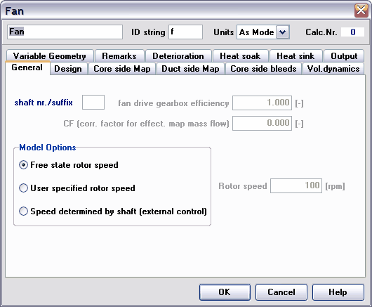
The fan component data form appears

| 2. | Select the General tab sheet and check that the shaft nr./suffix is set to 1. |
With this the fan is linked to the low pressure turbine, if the same shaft number is specified.
| 3. | Select the Design tab sheet. |
In this tab sheet all major design variables for the fan are specified.
| 4. | Set the design bypass ratio to 0.64. |
| 5. | Set the design rotational speed to 10000 at 100 %. |
| 6. | Set both the core side design pressure ratio and duct side design pressure ratio to 3.2. |
| 7. | Set both the core side design efficiency and duct side design efficiency to 0.8. |
| 8. | Select the Core side Map tab sheet. |
Here the map file for off-design calculations and the fan design point are specified.
| 9. | Click the Browse map files button, select the ABFANfanc.map file from the GSP standard directory and click the Open button. Select the storage switch to Local. |
| 10. | Set the map design Beta value to 0.6 and check if the map design rotor speed is set to 1. |
Now the fan core design point is set. The Beta parameter is a dimensionless map parameter explained in beta parameter.
| 11. | Optionally click the Show Graph button to view the component map and design point. |
| 12. | Select the Duct side Map tab sheet and repeat 9 to 11 with the ABFANfand.map file. |
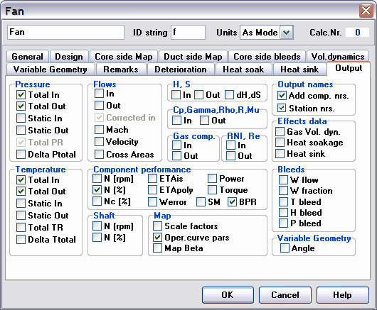
| 13. | Select the Output tab sheet |
In this tab sheet the requested output parameters for the used component are specified.

| 14. | Check Pressure Total Out, Temperature Total Out, Flows Corrected in, Turbo N [%] and Oper. curve pars. |
In the output table which will be generated after simulation, the total pressure and total temperature at the outlet of the fan core and duct are reported, as is the corrected mass flow at fan entry. By checking the Oper. curve pars several variables are automatically selected, enabling the viewing of the operating line in the off-design map.
| 15. | Click OK to close the fan component data form. |