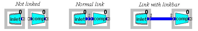
When building new models, components have to be arranged in a particular configuration in order to represent the actual gas turbine engine model in a model window. GSP uses linked objects represented by link icons to facilitate interaction among the components. The link elements are visualized by small rectangles on the components icons with double chevrons indicating the direction of data.
The user must position the components in a manner that the links touch each other. When a link can be established, the rectangles turn blue for gas path links, and black for control links.
When a certain distance between components is desired, a Link Bar may be used to establish the link over a larger distance. With the component pop-up menu, component icons and link bars can be rotated.