Building a GSP model is intended for the more experienced user. If you are a novice at using GSP, it is recommended that you start with running simulations with the existing sample models, as described in Running a simulation. Note that it usually is most practical to derive new models from existing or sample models. Open an existing model, adapt component data as described in Entering component data, and add or reconfigure components as necessary.
A new gas turbine engine model is built by configuring predefined generic components in a certain arrangement in a model panel using GSP's drag-and-drop interface. The components are dragged from component libraries onto a model window.
Use the File|New command from the Main window to open a new GSP project. In the new GSP project, go the the Reference model node in the project treeview to activate the Reference model configuration. On the right, an empty model window appears (if not, select the 'Model' panel by clicking the 'Model' tab or go to the Model menu and select Show Model Panel. Next, the gas turbine model is configured using simple drag-and-drop operations: select a component with the mouse from the standard component library, keep the mouse button pressed while dragging the component to the model window and release the mouse button to drop the component on the window. Drag more components from the libraries onto the window, and link them together using the link icons on the component icons.
Note that components can also be dragged, copied and moved to and from other existing model windows.
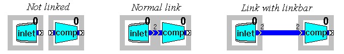
A particular gas turbine configuration is obtained by linking the components in the model window together in a corresponding arrangement. Components are linked by placing them adjacent to each other or using the link bar component. The links between components represent either
•gas path connections at user specified engine station numbers or,
•control inputs (such as a fuel flow signal from a fuel controller to a combustor component).
Other connections or relations among components such as shafts transmitting power or secondary air flows are specified using numbers in the component data and are not visible in the model window (see 5.2.1 and 5.2.2).
The chevrons on the link icons indicate the direction of gas flow or control input. GSP has defaults for specific (gas path) component entry and exit station numbers according to ARP 755A. When linking gas path links, GSP uses the default station number if both sides match (e.g. compressor exit and combustor entry station numbers are both 3), otherwise GSP requests the user to specify a number. Station numbers are also used to identify output parameters at particular engine stations.
Adapt the station numbers for the gas path links (click the link icons) if necessary. Fractional station numbers (e.g. 4.5 for between turbines) may be entered. If components are linked, the connection indicator turns dark blue for gas path links and black for control links, as shown in the following figures, and for gas path links, the user specified station number appears.
An example of a simple turbojet model is given by the TJET model.
If the new model has been completed, the component data must be entered.


