
The gas generator fuel control component offers a generic fuel control system model with PID speed control and maximum acceleration and minimum deceleration schedules. Many simple conventional (mechanical) gas generator rotor speed governors can be modeled accurately. For more complex (e.g. FADEC, Full Authority Digital Engine Control) control systems characteristics, the component is useful when detailed control aspects can be neglected, such as in gas turbine transient performance trade-off studies. For detailed models of complex control systems, usually custom components are required. Also for accurate transient simulation of modern multi-spool jet engine (e.g. turbofan engines) control systems, controlling both gas generator and fan rotor speeds, custom components are required.
Schedules
Three schedule tables must be specified:
| 1) | a PLA - Ndem schedule representing the relation between power lever angle PLA and demanded gas generator rotor speed (or corrected compressor rotor speed), |
| 2) | governor PID gain schedules including a reference value (WfPbref) al as functions of rotor speed (or corrected rotor speed), |
| 3) | Maximum acceleration and deceleration WfPb schedules as functions of rotor speed (or corrected rotor speed). |
Click the Graph button to see graphical presentations of the schedules. All schedules are represented by tables using linear interpolation. Note that outside the table range, values are extrapolated !
Scaling
All schedules are scaled to design point values. From the PLA design (in the Design tab sheet) the design Ndem is determined and scaled to the design rotor speeds specified for the compressor component. The scaling factor is saved and used for scaling between the actual Ndem table values and actual compressor speed. Also scaling factors are determined for the Wf/Pbref values in the PID schedule and the WfPbmin/max values in the maximum accel/decel schedules. Note that control characteristics (i.e. control components) from one engine can easily be used for another one, but simulation results (for WfPb for example) may deviate significantly from the schedule table values.
Control system input
There are up to 4 controller input parameters :
•Power Lever Angle (PLA),
•gas generator compressor entry temperature,
•total pressure of a user specified compressor bleed flow to represent burner pressure
•rotor speed.
Sensor dynamics for rotor speed, pressure and temperature are modeled assuming first order lag with user specified time constants.
The calculation of fuel flow Wf is performed according the chart below.
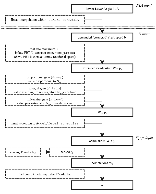
The controller governs a demanded rotor speed level, which is a function of PLA. Depending on the Corrected Ndem option in the Schedules tab sheet, the demanded rotor speed schedule represents either actual (Ndem) or compressor entry corrected rotor speed (Ncdem=Ndem/vq).
Demanded rotor speed Ndem (or Ncdem) is controlled using a PID controller with P(proportional), I(integral) and D(differential) gains depending on scheduled rotor speed Nsch. Nsch may either be Ndem or Ncdem, depending on the user specified option Corrected N in Gov. and A/D sched option in the Schedules tab sheet.
The PID controller outputs a Wf/Pb signal representing fuel flow divided by burner pressure. The PID output is based on the rotor speed error (Nerror = Nsch - N) and is added to the reference WfPb (Wf/Pbref), which is a function of Ndem.
The integrator in the PID controller is a reset integrator, resetting the integrator signal to zero upon input signal sign change. This may not apply to all PID controllers, for other PID logic, custom control components are required.
As an option, Wf/Pb corrected to compressor entry temperature may be used instead (i.e. Wf/(Pb.vq) depending on the Correct Wf/Pb to Ttin compressor option in the Schedules tab sheet.
The WfPb (or corrected Wf/Pb) signal is limited by the maximum acceleration or deceleration schedule, which are user specified functions of actual rotor speed or corrected rotor speed, depending on the user specified option Corrected N in Gov. and A/D sched option in the Schedules tab sheet.
From the resulting limited Wf/Pb, commanded fuel flow Wfcalc is calculated by multiplication with Pb (and for corrected Wf/Pb also with vq).
Actual fuel flow Wf is calculated using a first order lag transfer function with a user specified time constant to simulate fuel pump dynamic response.
Automatic flat rating control can be used to limit power setting, based on maintaining constant (maximum) corrected rotor speed at outside air (or compressor entry) temperatures below the flat rated temperature FRT. The maximum corrected rotor speed is defined the maximum rotor speed at FRT.
In the chart, the following remarks apply:
•Ndem is corrected for the compressor entry temperature if Corrected Ndem is checked
•Flat rating is only applicable if Auto Flat Rated Power Limiting is checked
•Nerror is the difference between N and demanded N
Other options:
•Fully Trimmed steady state (no droop)
Check this option if fully trimmed steady state operating points (proportional gas generator speed governor droop error fully compensated by trimmer) need to be calculated. This enables calculation of operating points at user or control system specified rotor speeds and shaft loads. With this option, GSP calculates the final integrator output signal at the fully trimmed steady state condition (i.e. at infinite time).
Both a state and an error variable are added with the 'Fully trimmed steady state' option: the trimmer output then is a state and the shaft speed error (Ndemand-N) is the error. No additional component needs to be modified and fully steady state points with a fully trimmed gas generator speed can be calculated.
Note that this only works if the integral (I) gains in the PID controller are non-zero and that, with this option, transient simulations are inhibited !
•F trim reset to 0 Nerror dead band
This option is to control the dead band for the integrator reset upon sign change of the integrator input signal (i.e. Nerror). Integrator reset only occurs after Nerror has passed zero with the specified value.
Note: steady state and steady state series calculations may become problematic when control system components with engine parameter feedback depending on time (such as Gas Generator Fuel control and Turboshaft Fuel control components) are used in the model. The best way to calculate a steady state point then is to stabilize at the particular operating point using a transient calculation first before performing a steady state calculation.


