To assess the off-design behaviour of gas turbine components, component maps are used to define the off-design characteristics. When the components are grouped to form a gas turbine the range of possible operating conditions depends on the equilibrium of the gas turbine as a whole. The equilibrium points can be plotted in the component charateristics map to form the equilibrium operating (running) line.
To demonstrate the operating line usage in the compressor, a running line for a TJET model has been constructed using a decreasing fuel flow sweep. Figure 1 shows the compressor off-design charateristics for the TJET. The blue line denotes the actual (real) compressor running line. Imagine that we do not know the operating line and assume that the operating line is linear (red line).
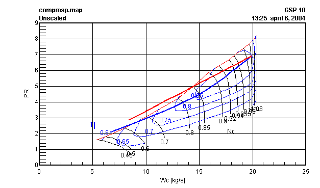
figure 1 Compressor Map; actual TJET compressor running line (blue line), assumed TJET compressor operating line (red line)
Since the option "No Massflow Error Equation" needs to be checked to deactivate the turbine massflow error equation (to obtain a solvable equation system) the error increases the further the asumed operating line deviates from the actual operating line. In case the operating line is the actual running line of the engine (or close to), the error will remain very small (can be visualised through the option Werror on the turbine output tab sheet). Figure 2 shows the massflow error for the actual and the assumed operating line.
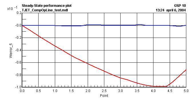
Figure 2 Turbine massflow error result
Figure 2 clearly shows that the further the assumed operating line is away from the actual operating line the massflow error of the turbine increases.


