
The heat exchanger component is used to simulate heat transfer between two gas flows in a heat exchanger. In a gas turbine heat exchangers are often used as "recuperators", transferring heat from the exhaust gasses to the combustor entry air to improve cycle efficiency.
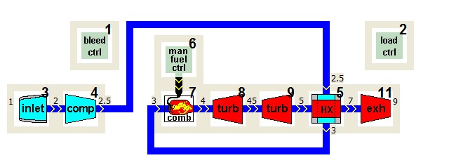
The two flow passages are identified by numbers 1 (hot flow) and 2 (cold flow). These numbers are also used to identify output parameters such as for example the pressure ratio in passage 2 in the figure below with PR2_4 ( _4 indicating component 4).
For the design point, either design point heat flow rate or the temperature change in the passage first entered by the gas (i.e. calculation procedure) is specified. Be careful to enter the right signs for the design heat flow (positive for heat from passage 1 to 2).
In the TSHAFTrecup sample project in the figure below for example, the first passage is the number 2 passage receiving air from the compressor.
Off-design heat transfer is determined by a component map providing heat exchanger effectiveness as a function of passage 1 and 2 mass flow rates. As with other maps, the heat effectiveness map is automatically scaled to the engine design point heat flow and passage 1 and 2 mass flows using the map design point.
In GSP, the heat exchanger / recuperator component definition of effectiveness is fully enthalpy based:
Eff = Q / Qmax
with Q = the actual steady-state heat flow from flow 1 to flow 2 :
Q = Wh * ( H(Th_in, GCh_in) - H(Th_out, GCh_out) )
or Q = Wc * ( H(Tc_out, GCc_out) - H(Tc_in, GCc_in) )
and Q max = Wcpmin * ( H(Th_in, GCcpmin) - H(Tc_in, GCcpmin) )
where:
Wh is the hot side mass flow, Wc is the cold side mass flow,
H(T.. ,GC..) is the GSP enthalpy function of temperature (i.e. varying Cp) taking into account gas composition GCh (hot flow) and GCc (cold flow),
Th_in/out are the hot side in/out total temperatures
Tc_in/out are the cold side in/out total temperatures
Wcpmin is the mass flow of the flow with the lowest product W*Cpin (mass flow * entry value for Cp).
GCcpmin is the gas composition of the flow with the lowest product W*Cpin (mass flow * entry value for Cp).
Internal heat soakage effects (heat capacity of 'wall' material between two gas flows) can be modeled by specifying:
•effective contact surface [m^2]
•design film coefficient ratio
•wall effective mass [kg]
•wall material specific heat [J/kg/K]
•effective wall thickness [m]
•wall material thermal conductivity [W/m/K]
•average wall temperature time constant
For both passages volume effects can be calculated and pressure losses can be specified. Note that the heat soakage (transient) and heat sink (steady-state and transient) effects are applied to the 2 gas flows without taking into account the heat flux between them. In that sense the heat soakage effect can be considered as 'Outside wall heat soakage effect' and the heat sink heat transfer is simply happening between the flow (flow 1 or flow 2) and the specified Heat sink. For heat soakage effects of the material between the two gases, specify the data in the Internal Heat soak tab sheet.


