gsphelp  Compressor map

<< Click to Display Table of Contents >>

Navigation:  GSP components > Component Libraries > Gas Path Components > Gas Path Component Library > Compressor >

gsphelp  Compressor map

Previous pageReturn to chapter overviewNext page

The compressor characteristics are represented in the compressor component map. The map displays the relation between 4 parameters corrected for entry conditions: corrected rotor speed Nc, pressure ratio PR, corrected mass flow Wc and isentropic efficiency ETAc. In GSP, the beta parameter composed of Wc and PR is used for better simulation stability.


The figure below shows an example of a compressor map

GSP11_CompressorMap


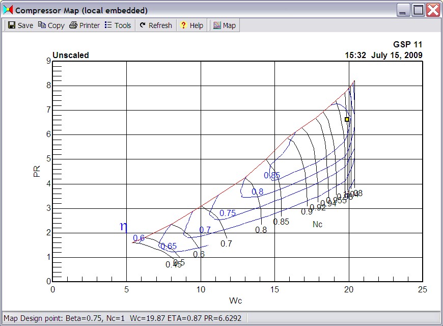
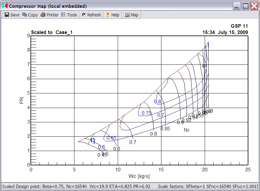
Note that the little yellow rectangle represents the map design point (DP) to which the engine design point is scaled. If the map graph is scaled using the Map | Scale to model design point menu option, then naturally the rectangle represents the actual engine DP. See example of a scaled compressor map below.

compressormapscaled