Quick start basics - Building a GSP model .
After you have started GSP and you have opened the TJET.mdl model (see "Opening a model"), or alternatively proceed from the project created in the previous two examples ("Your first simulation session" or "Adapting engine characteristics").
To obtain the afterburning turbofan configuration, do the following:
| 1. | A new configuration needs to be created under the "ReferenceModel" to allow adding of components and setting of reference/design data. Name this configuration "ABFAN". |
We are about to change this configurations engine configuration by adding the additional components to the model panel (drag-and-drop from the component libraries), and arrange them according to the desired displayed (below) gas turbine configuration. Look for appropriate components in the Gas Path Component Library (Duct, Turbine, Several component Link bars), Multi in/out Component Library (Fan, Mixer), Standard Controls Component Library (Manual afterburner fuel control, Manual Variable Exhaust Nozzle Control).
| 2. | Select all components by clicking with the mouse inside the model panel area, keeping the mouse button pressed and drawing a rectangle around all components. |
| 3. | Move the components by clicking with the mouse on any component, keeping the mouse button pressed and moving the components to the right. Unselect all components by clicking somewhere in the model panel area, but not on one of the components. |
| 4. | Select the inlet component and move it to the left to make room to insert the fan component. |
| 5. | Select the fan component with the mouse from the Multi in/out Component Library, keep the mouse button pressed while dragging the component to the model panel and release the mouse button to drop the component on the form in between the inlet and the compressor. |
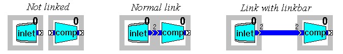
| 6. | Link the fan component to the inlet and enter 2 as the station number (if not done automatically). |
Components are linked by placing them adjacent to each other or using the link bar component. The requested station number is the designator of the output of the gasturbine component. If components are linked, the connection indicator turns dark blue and the station number appears as displayed.
| 7. | Link the fan component to the compressor (move inlet and fan as stated above), unselect the components and set the station number to 25. |
Be sure that no components are selected, otherwise no stations can be selected.
| 8. | Select the duct component from the standard library, connect it to the fan bypass outlet and set the station number to 27. |
| If there is no room, enlarge the window, select all components and move them down. |
| 10. | Select the link bar component from the Gas Path Component Library and place it anywhere on the model window area, but not on a component. |
| 11. | Connect the fuel control component to the combustor component with the link bar. |
The length of the link bar can be changed by dragging one of the ends like the standard Windows enlarging operation. If successful, the link bar turns black. No station number is required.
| 12. | Select, move and drop the remaining components and input and change the station numbers to create the model displayed above, with the exception of the exhaust control component. |
| If the model panel is too small, simply enlarge it by dragging the window borders. |
| 13. | Select the exhaust component on the model window and enter the component data sheet by double-clicking the component or right-clicking it and selecting Edit. |
| 14. | Select the General tab sheet and check the Variable area nozzle radio button in the Model Options. |
The text Use Nozzle control component ! appears.
| 15. | Click the OK button to close the exhaust component data sheet. |
A connector is now visible at the top of the exhaust component icon.
| 16. | Select the manual variable exhaust nozzle control component (VEN) from the control library and connect it to the exhaust component. |
If the new model has been completely build, the component data must be entered.