![]() Starting a simulation session
Starting a simulation session
![]() Starting a simulation session
Starting a simulation session
|
<< Click to Display Table of Contents >>
|
  
|
Quick start basics - Your first simulation session .
| 1. | Our reference model of the TJET is stored in the Base configuration model (the model root) node. From this base configuration model we will perform some performance analysis. First add a configuration to the Base configuration model configuration. The reason for adding an extra layer is that this might be very useful if the model should be changed later, and therefore not compromise the original reference/base configuration model. Adding a configuration can be done using one of the 3 different options (described here) to edit the project tree view (the most convenient way is to press the GSP logo button of the toolbar just above the project tree). Confirm the base configuration model changes (if any) dialog and enter the configuration name "TJET_Config" in the Config Name dialog. Second, add a case to the reference model by using one of the 3 different options (described here) to edit the project tree view. Confirm the configuration model changes (if any) dialog and enter the case model name "Design case" in the Case Name dialog and set the case type to design by selecting Design from the drop down selection box in the right column next to the case name. Press the run button (green arrow) or alternatively press F9 to start the simulation. |
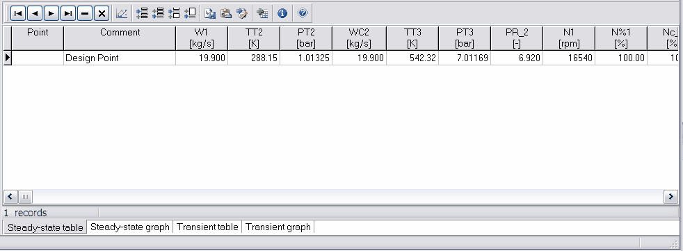
Simulation results will be generated in the Steady State output table, located default in the lower right corner of the project window (see figure below).
To obtain a reference state for the off-design calculations, the actual gasturbine configuration must be defined and the components must be "sized" with a design point calculation. As usually defined, the model design point is the sea-level standard static rated thrust or power, which usually is the rated maximum take-off thrust.
| 2. | Study the values in the table by scrolling left and right using the bottom scroll bar. |
The table shows the design point steady state performance data on the first row. On the far right net thrust and SFC can be found. The gas path output parameters shown here have been selected in the respective components' Output tab sheet of the data entry window of each component. System performance parameters are set on Options|Output...|Output parameters|System Performance.